Modular Electrical Power System 2
Price on request
- Modular solution – multiple PC104 form factor board, ideal for 3U platforms and up
- Communication over two independent I2C or UART interfaces, SPI optional
- FRAM-based MCUs for improved radiation tolerance
- Hardware over-current protection and hardware-based maximum power point tracking
- Hardware Supervisor including Watchdog
- Solar Panel interface utilizes GaN-FETs
- Output load channels:
- Buck regulated power channels
- Over-current and reverse-current protection in hardware
- Over-voltage protection through TVS diodes
- Turn on voltage ramp control (soft start)
- Software configurable auto enable and latch-off retry enable timings
- Accurate voltage, current and power sensing on each channel
- Rich housekeeping telemetry available
- Very low idle consumption when no enabled output channels
Description
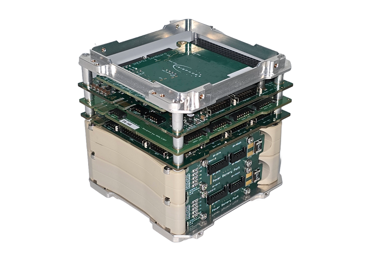
The ISIS Modular Electrical Power System (IMEPS) is the second-generation modular EPS designed by ISISPACE, targeting larger nano-satellites and microsatellites from 3U upwards. Using recent high-performance technology, the IMEPS Electrical Power System provides improved efficiency over the previous version while minimizing EMI. The modular architecture allows the EPS to be tailored to the needs of the platform without needing customization. The distributed design philosophy that underpins the IMEPS design allows unprecedented flexibility in output bus count and voltage and enables tailorable redundancy to be applied for selectable parts of the platform, depending on the needs of the mission.
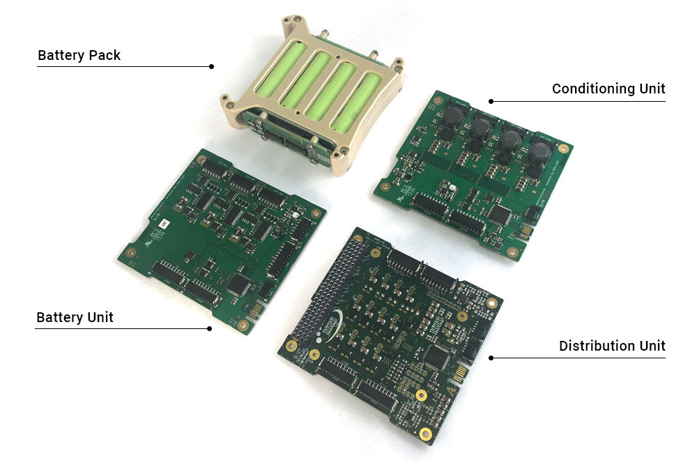
The IMEPS Electrical Power System consists of four types of elements:
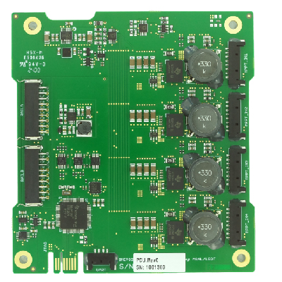
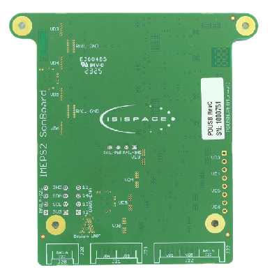
- ISIS Power Conditioning Unit (IPCU) – Solar panel input to the common power rail
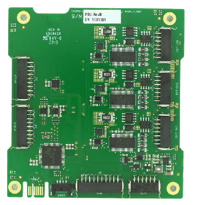
- ISIS Power Battery Unit (IPBU) – Secondary power storage and retrieval control
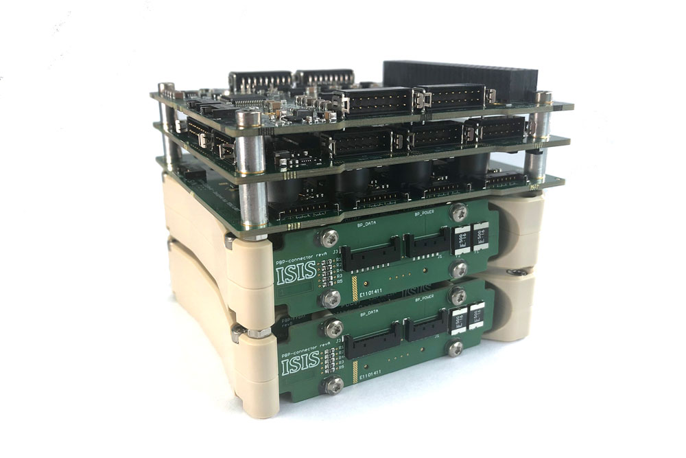
- ISIS Power Battery Pack (IPBP) – Battery holder with integrated fuse
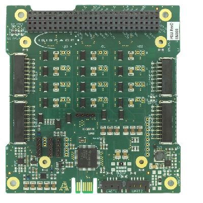
- ISIS Power Distribution Unit (IPDU) – Power regulation to attached subsystem loads
One or more of each of these units can be combined to form the platform EPS.
Specifications
| Mass: | IPCU: 58g
IPBP: 252.0g IPBU: 48.7g IPDU: 58g (incl. Full CSKB) |
| Volume: | IPBP: 90 x 96 x 21 mm
IPCU: 90 x 96 x 12 mm IPBU: 90 x 96 x 10 mm IPDU: 90 x 96 x 14 mm |
| Operating temperature: | -20 to +70 deg C |
| Data interfaces: | I2C, UART,SPI optional |
| Power Battery Pack (IPBP) | Lithium-Ion |
| Operating Voltage Vbat:8V – 16.0V | |
| Storage capacity: 45Wh per pack (4 cells) | |
| Battery Pack Configuration: 4 cells in series | |
| 10A fuse per pack | |
| Power Conditioning Unit (IPCU) | 4x MPPT channels per board |
| Maximum Input Current: 3A per channel | |
| Output Voltage: 16V (other voltages upon request) | |
| Max Input Power (per channel): 39W (5 series, 6 parallel solar cell strings) | |
| Power Battery Unit (IPBU) | Max Input Power: 25.6W at 16V |
| Max Output Power: 64W at 16V | |
| Battery Heating & Balancing | |
| Telemetry: total input/output current, voltage, power, cell voltage, temperature | |
| Power Distribution Unit (IPDU) | 3x Switchable VD0 Battery voltage lines (12.8V-16.0V) |
| 1x Permanent VD0 Battery voltage lines (12.8V-16.0V) | |
| 4x Switchable VD1 voltage lines (3V3, 5V or custom up to 12V) | |
| Max current of 3A per line | |
| 4x Max current of 4A (continuous) and 6A (peak) for VD0, VD1 and VD2 |
Configuration
Additional – Battery packs
- Up to three battery packs (IPBP) per battery unit board (IPBU)
- Each additional IPBP adds 45Wh battery storage
- Multiple IPBP’s and IPBU’s can be placed in parallel for redundancy
Additional – Conditioning Units
- Each additional conditioning unit (IPCU) allows for further 4x 39W MPPT channels
- Multiple IPCU’s can be placed in parallel for redundancy
Additional – Distribution Units
- Each additional distribution unit (IPDU) allows for a further
- 1x permanent line at Vbat (12.8V – 16V)
- 3x switchable lines at Vbat (12.8V – 16V)
- 2x user-defined voltages (up to 12V)
- Each user-defined voltage has 4x switchable lines
- Multiple IPDU’s can be placed in parallel for redundancy
Qualification and Acceptance testing
| Test | QT | AT |
| Functional | ✓ | ✓ |
| Vibration | ✓ | ‐ |
| Mechanical Shock | ✓ | ‐ |
| Thermal Cycling | ✓ | ✓ |
| Thermal Vacuum | ✓ | ‐ |
*QT is performed on the design/qualification model
*AT is performed on the unit to be shipped
FAQ
Is the ISISPACE Electrical Power System ISS compliant?
Yes, please select this option when ordering.

